Expertise: Emissions

  • Instrument Gas to Instrument Air Conversion

    Instrument Gas to Instrument Air Conversion

    The Challenge

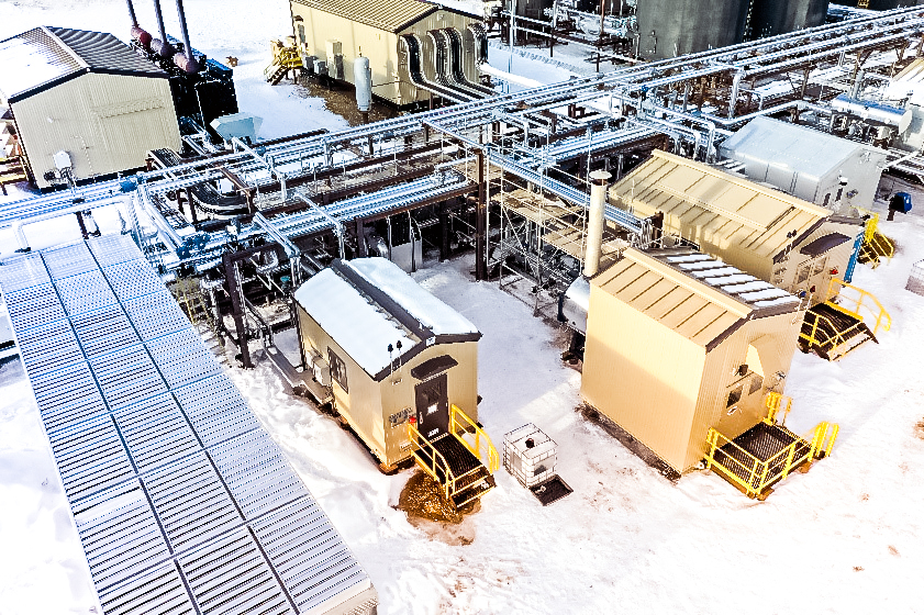
    The Client needed to convert the instrument gas devices at (4) natural gas compression facilities in Oklahoma to instrument air service in a 6-month period.

    OOOO(b) requires that process controllers emit no identifiable emissions. Instrument air systems are inherently emissions free, so they are not subject to requirements specified in subpart 60.5390b.

    The Solution

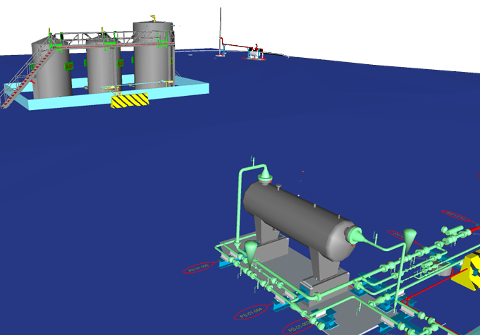
    CANUSA EPC conducted site visits to audit all the instrument gas users at the facility, as-build the P&IDs for IA users, and validate facility electrical capacity to add an instrument air skid. Sizing requirements for the instrument air compressor skid were provided to account for all users and start air for the natural gas compressors.

    The design and construction packages were executed in sequential order to meet accelerated schedule deadlines.

    Engineering

    • Walk down (4) facilities
    • Instrument demand study
      • Start air evaluation
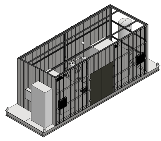
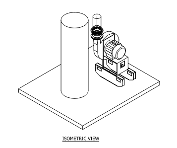
    • Instrument air skid specifications
      • Dual compressor design for
    • Recommend electrical upgrades

    Design

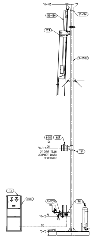
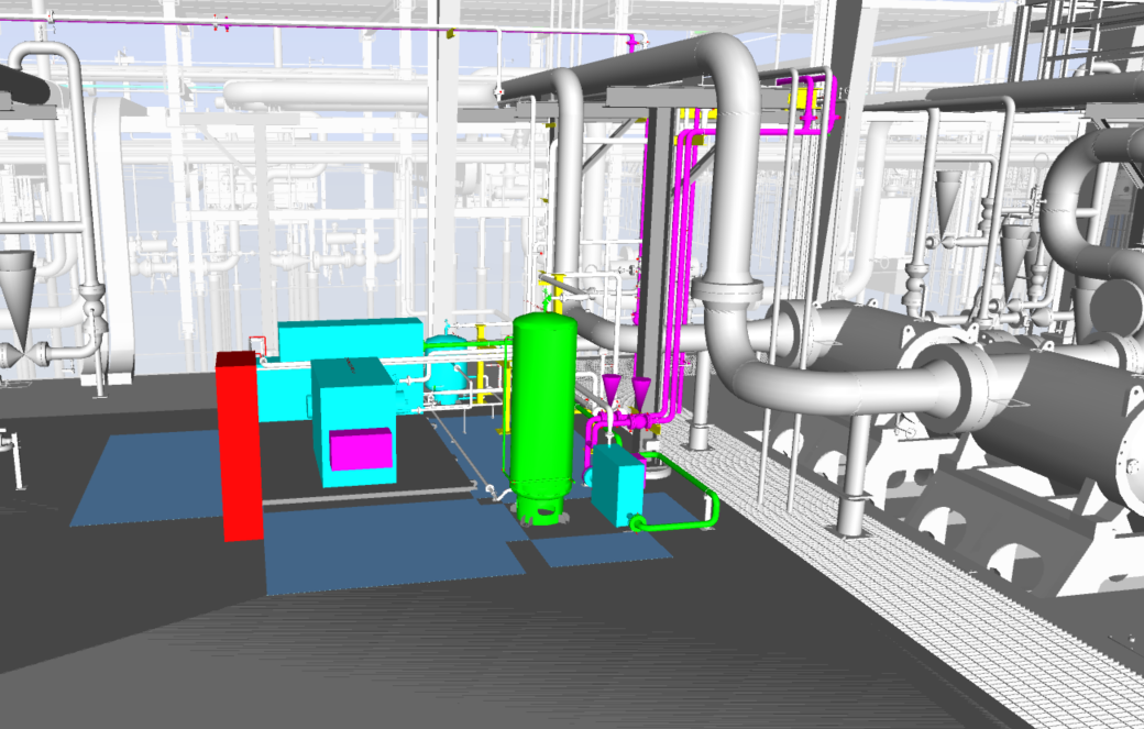
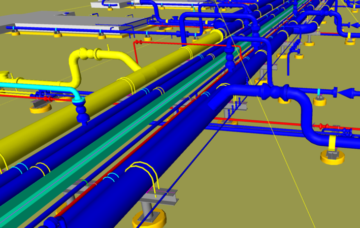
    • Isometric riser details for IA user areas
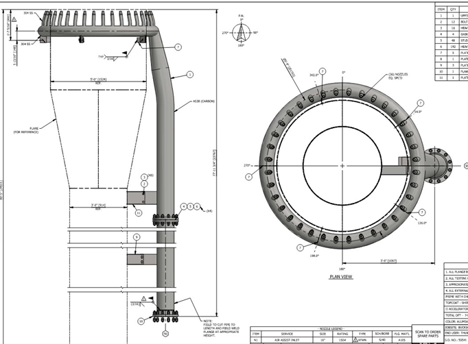
    • Header design to account for future start air
    • Electrical and utility upgrades

    The Results

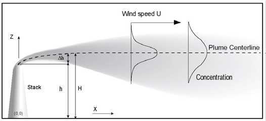
    Reduction in fugitive emissions and venting from previous IG users and compression start-up

    • Successfully achieved reduction of all instrument gas users
    • Calculated emissions reduction of 153 MTPY of methane
    • Compliance with OOOO(b) section 60.5390b
    • 25% reduction in engineering design on a site basis
  • Tank Venting Emissions Reduction

    Tank Venting Emissions Reduction

    The Challenge

    The Client was venting excessive vapors from their produced water tank battery due to higher operating pressure in their inlet separator. Operations had determined that the pressure drop between the slug catcher and the storage tank was resulting in entrained gas venting above OOOO(b) limits.

    The Solution

    CANUSA EPC provided engineering and design to install an emission control device. An intermediate knockout drum and combustor were added to the facility. Liquids were routed from the slug catcher to the lower-pressure intermediate knockout, allowing more gases to flash off before sending the remaining liquids to the water tanks. All flashed gases were sent to the combustor.

    Engineering

    • Flare specification
    • Re-purposed knockout drum evaluation
    • Instrumentation and control systems added
    • Saddle design and flare guy wire anchoring solution

    Design

    • 3D Modeling of piping, structural steel, and foundations
    • Piping isometrics
    • Pipe support and foundation details

    The Results

    Reduction in vented vapors from the tank battery

    • Reduced direct venting methane by 10 TPY
    • Alternative solution for recycle of entrained gas to inlet
    • Compliance with OOOOb section 60.5365b(e)
  • Amine Vent Dispersion

    Amine Vent Dispersion

    The Challenge

    The Client was experiencing shutdown trips in their amine processing area from hydrogen sulfide sensors due to increased H2S in the inlet gas. During calm ambient conditions (e.g. no wind), the gas from the vent stack can migrate to grade and present safety concerns for the onsite operators and exceed the NIOSH REL and OSHA PEL 10-minute exposure limits.

    The Solution

    CANUSA EPC evaluated various options from thermal oxidizers, vent stack blowers, and H2S scavengers as solutions to reduce the instances where H2S was causing facility shutdowns. The solution selected was a modified blower vent tip system to increase the velocity of the exit gas to elevate the concentrated gas high enough to disperse to non-detectable levels by the time it reached safety sensors.

    Engineering:

    • Blower specification
    • Dispersion modeling
    • Electrical system additions
    • Vent structural steel design for blower

    Procurement:

    • VFD Specification
    • Blower package evaluation
    • Dispersion modeling
    • Construction package bids

    The Results

    Reduction in ground measurements of H2S exceeding the 20 ppm sensor shutdown

    • Reduced conditions where operators are exposed to H2S limits above OSHA
    • Mitigated instances of shutdown related to inadequate dispersion of H2S
  • Turbine Seal Gas Capture

    Turbine Seal Gas Capture

    The Challenge

    The Client agreed to mitigate emissions from turbine units seal gas system at one of their compression sites to satisfy an EPA consent decree regarding the Clean Air Act and the Colorado Air Pollution Prevention and Control Act. Per the terms of the agreement, the Client was required to install a seal gas capture system within 90 days of receiving the dry seal recompression unit.

    The Solution

    CANUSA EPC worked with the Client and packager of the dry seal recompression system to develop an engineering and design package for the installation of the system.

    Multi-Discipline Engineering

    • Electrical tie-in of 40 HP Motor
    • PSV sizing for new relief scenarios
    • Piping modeling for discharge into plant inlet to recover the gas
    • Automation design to integrate with station controls

    Procurement

    • VFD and Cable specification
    • Pressure Instrumentation
    • Construction Bid Walkdowns

    The Results

    Deployed the first seal gas system in the fleet

    • Installation of a single capture unit for seal gas of two turbine units

    Reduction in fugitive methane emissions

    • Reduction in venting emissions of 49.3 mton of CO2e/day
  • Reduced Emissions with Heat Recovery

    Reduced Emissions with Heat Recovery

    The Challenge

    CANUSA EPC was tasked with adding heat trace (piping freeze protection) and building heat to a gas plant. It was noted that there was a large amount of waste heat being released into the atmosphere from cooling oil at the adjacent oil battery. The Client wanted to investigate if there were options to utilize this waste heat, reducing operating costs and GHG emissions. The heat source was provided at 60°C where typical glycol heating systems operate at a minimum of 90°C.

    The Solution

    The heat duty required for providing heat to the facility was approx. 3.5MMBTU/hr and the heat duty available from cooling the oil was 10MMBTU/hr. CANUSA EPC designed a unique system based on a proprietary calculation model to utilize the warm glycol exiting the oil cooler at 60°C.

    Developing a Plan to Meet Client Expectations

    • Leveraged our in-house process and design experts
    • Developed and managed installation scope to meet existing project schedule

    Sourced New Equipment:

    • Glycol boiler
    • Glycol cooler
    • Waste heat recovery building
    • Glycol pump
    • Glycol heat trace and supply/return manifolds
    • Glycol building heaters

    Execute Value Engineering to Support the Project Schedule

    • Rigorous heat duty and heat transfer calculations to maximize efficiency
    • Hydraulic modeling of the GHT system
    • GHT and manifold isometrics to control costs of installation

    The Results

    Lowered emissions of the facilities

    • Eliminated 4.4 MTPD of CO2 equivalent emissions

    Lowered annual facility operating costs

    • Estimated $100,000+ CDN/year OpEx savings

    Integrated waste heat recovery

    • Designed and implemented a GHT system to operate with 60⁰C warm glycol