Expertise: EPC Updates

  • Energy By Design : How Power Markets Are Shaping the Next Generation of Industrial Projects

    Energy By Design : How Power Markets Are Shaping the Next Generation of Industrial Projects

    Summary

    Explore how surging U.S. electricity demand and record-breaking capacity market signals, like PJM’s $67 billion wake-up call, are reshaping the next generation of industrial energy infrastructure projects across North America. Examine key projects developing behind the meter facility and utility projects and the market forces driving unprecedented investment in onsite power generation, natural gas processing, and energy facility development. The Energy by Design presentation delivers actionable insights for energy professionals navigating the evolving power landscape.

  • Navigating Colorado AQCC Regulation 22: How CO2 Regulations is Impacting Natural Gas Processing Plants

    Navigating Colorado AQCC Regulation 22: How CO2 Regulations is Impacting Natural Gas Processing Plants

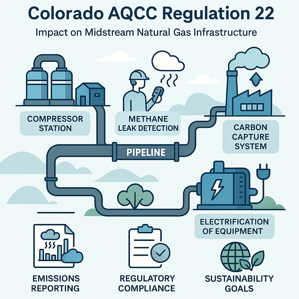
    As Colorado increases its efforts to combat climate change, the regulatory landscape for industrial operators (particularly in the natural gas processing plant and gathering system sectors) is evolving rapidly. The latest development, Colorado Air Quality Control Commission (AQCC) Regulation 22, introduces stringent greenhouse gas (GHG) reporting and reduction mandates that will significantly impact how midstream infrastructure is designed, operated, and maintained.

    Understanding Regulation 22

    Regulation 22, formally titled Colorado Greenhouse Gas Reporting and Emission Reduction Requirements (5 CCR 1001-26), establishes a comprehensive framework for monitoring, reporting, and ultimately reducing GHG emissions across multiple sectors of the state’s economy. For midstream operators (those responsible for gathering systems, natural gas processing plants, and transportation), this regulation will require balancing the development needs of producers and the emissions caps related to GHGs.

    The rule mandates that Annual GHG reporting will be required for facilities that emit over 25,000 metric tons of CO₂e per year, as well as multiple sources if they fall below the federal reporting thresholds (e.g., the 25,000 metric ton CO₂e threshold under EPA’s 40 CFR Part 98).

    Emission reduction targets are aligned with Colorado’s broader climate goals: a 26% reduction by 2025, 50% by 2030, and 90% by 2050 (from 2005 levels) established under  HB 19-1261.

    On February 14, 2025, regulatory provisions became effective requiring every midstream company to participate in the emissions reduction program. They must achieve a collective midstream segment cap of 3,930,228 metric tons CO₂e by December 31, 2030, and maintain company-specific caps annually thereafter.

    Implications for Midstream Project Development

    From a project development perspective, Regulation 22, which was adopted in October 2024 and went into effect in early 2025, requires a paradigm shift. No longer can emissions be an afterthought. GHG emission reduction and methane reduction must be embedded from the earliest stages of project planning.

    Here’s what midstream developers will need to consider with their emissions planning:

    Carbon Footprint Assessments for New and Existing Assets

    Developers must evaluate the lifecycle emissions of both current and planned infrastructure. This includes emissions from:

    • Compressors and natural gas processing plants
    • Fugitive methane leaks from gathering systems and pipelines
    • Combustion sources such as flares and engines

    Integrating carbon modeling tools into the front-end engineering design (FEED) process is now essential to determine how overall emissions levels will be impacted for the operator. The company-specific emissions caps are calculated using each operator’s 2021 MFCE GHG emissions.  October 2025 will require reporting under this program.

    Technology Integration for Emission Reduction at Existing Assets

    To meet reduction targets, midstream operators will consider solutions to lower the overall GHG emissions:

    • Electrification of engines at compressor stations and natural gas processing plants
    • Deployment of low-bleed or zero-bleed pneumatic devices
    • Advanced leak detection and repair (LDAR) programs
    • Carbon capture and storage (CCS) feasibility for large emitters

    Operators will expect to see increased CapEx costs for compliance with marginal increases in processing capacity.  Some assets may be consolidated and decommissioned before the planned end of useful life. Client will focus on reducing their methane emissions first, considered 25 times more potent than CO2 emissions. CANUSA EPC has various solutions documented for ideas, check out a novel capture application for Turbine Seal Gas Capture.

    Regulatory Compliance Strategy

    Operators must establish robust compliance systems that include:

    • Real-time emissions monitoring
    • Accurate data collection and reporting mechanisms
    • Internal audits and third-party verification

    Failure to comply could result in penalties and reputational damage, especially as public scrutiny of fossil fuel infrastructure intensifies.

    Civil penalties for midstream operators, under C.R.S. § 25-7-122, outline that violators may face civil penalties of up to $47,357 per day, per violation, with the amount adjusted annually for inflation. These penalties apply to a wide range of noncompliance issues, including failure to meet greenhouse gas (GHG) reduction targets, inadequate emissions reporting, and violations of leak detection and repair (LDAR) or combustion control requirements. In severe cases, the Colorado Department of Public Health and Environment (CDPHE) may also seek injunctive relief through the courts to compel compliance or halt operations.

    In egregious circumstances (such as willful misconduct, repeated violations, or incidents causing serious harm), operators may also face permit suspension or revocation under C.R.S. § 34-60-121, enforced by the Energy and Carbon Management Commission. While this statute is relevant to upstream operators, it is not directly applicable to midstream GHG violations under Regulation 22 is not clearly defined. These consequences underscore the importance of strict regulatory compliance, accurate emissions tracking, and timely communication with regulators.

    Looking Ahead for Natural Gas Processing Plants

    Colorado’s Regulation 22 is not just a regulatory hurdle—it’s a signal of the energy transition underway. For midstream operators, aligning with these mandates is not only about compliance but also about future-proofing assets and maintaining social license to operate.

    CANUSA EPC’s Role in Supporting Emissions Reductions

    At CANUSA EPC, we understand the complexities of midstream development in a carbon-constrained world. Our multidisciplinary teams are equipped to:

    • Conduct GHG impact assessments
    • Design low-emission natural gas processing plants
    • Integrate carbon capture and methane reduction technologies
    • Engineer and plan electrical system upgrades

    Have any questions or concerns?

    Reach out to our team or start a free Class V estimate today to evaluate pathways to low-cost compliance for lower emission operations.


    Author(s)

    Forrest Churchill


    External Sources:

    https://www.sos.state.co.us/CCR/GenerateRulePdf.do?ruleVersionId=11724&fileName=5%20CCR%201001-26

    https://www.sos.state.co.us/CCR/GenerateRulePdf.do?ruleVersionId=12032&fileName=5%20CCR%201001-9

    https://cdphe.colorado.gov/changes-to-colorados-greenhouse-gas-reporting-requirements

    https://leg.colorado.gov/bills/HB19-1261

    https://www.sos.state.co.us/CCR/GenerateRulePdf.do?ruleVersionId=11843&fileName=5%20CCR%201001-9

  • One Big Beautiful Bill Boosts 45Q to $85/ton for CO₂-EOR with Geological Storage

    One Big Beautiful Bill Boosts 45Q to $85/ton for CO₂-EOR with Geological Storage

    The recently passed One Big Beautiful Bill Act preserved and enhanced carbon capture and storage (CCS) opportunities. One of the most impactful provisions for carbon capture is the expansion of the 45Q tax credit to $85 per metric ton for CO₂ used in Enhanced Oil Recovery (EOR) when the CO₂ is permanently stored in geological formations. 

    This update significantly improves the financial outlook for oil and gas developers pursuing CO₂-EOR projects that meet geological sequestration criteria. In this article, we break down the implications of this policy shift and how project developers can capitalize on it. 


    What’s New in 45Q Under the One Big Beautiful Bill? 

    The One Big Beautiful Bill Act preserves and enhances the 45Q tax credit structure, with a critical clarification: CO₂ used in EOR now qualifies for the full $85/ton credit if it is geologically sequestered. This aligns EOR with saline storage projects in terms of credit value, provided the CO₂ is not vented or recycled but permanently stored underground in accordance with the EPA Class VI well regulations. 

    Key Provisions:

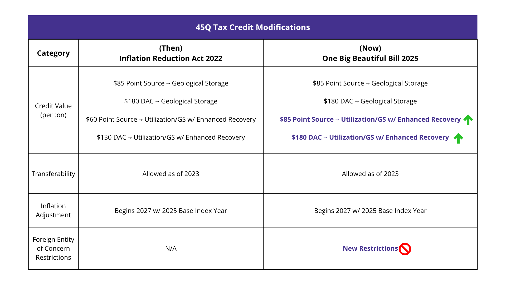
    • $85/ton for CO₂ captured and geologically stored, including via EOR 
    • $60/ton remains for CO₂ used in EOR without geological storage 
    • Transferability and direct pay options remain intact 
    • No sunset clause, offering long-term certainty for developers 

    This change reflects growing recognition of EOR’s role in both emissions reduction and domestic energy production. 


    Three 45Q Benefits for CO2-EOR Project Developers 

    1. Higher Credit Value = Better IRR 

    The jump from $60 to $85/ton for qualifying EOR projects can significantly improve project economics. For example, a facility capturing 500,000 tons of CO₂ annually, means an additional $12.5 million/year in direct payments. 

    2. Geological Storage Is Now a Strategic Differentiator 

    Projects that integrate Class VI-compliant injection wells and robust monitoring, reporting, and verification (MRV) protocols can now access the higher credit tier. This incentivizes developers to design for permanence and compliance from day one. 

    3. Financing Becomes More Attractive 

    With higher credit values and continued transferability, tax equity investors are more likely to participate. This opens the door for alternative financing solutions like non-recourse project financing and joint ventures. 

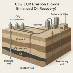
    Animated Image of CO2-EOR System Diagram

    Modular Deployment Reduces Risk and Cost in 45Q-Qualified Projects 

    CO2 projects requirements still incentivize modular execution. Incorporating modular process packages and construction not only reduces risk related to field construction, it’s a strategic tool for moving scope that is governed by 45Q labor requirements onsite to offsite scope; providing lower costs overall and less liability due to prevailing wage. 


    Why Modular Execution Matters: 

    Reducing Risk for 45Q Wage Requirements

    • Offsite labor is not subject to prevailing wage reporting or apprenticeship metrics, allowing the project to source market rate labor offsite and lowering the burden cost for the project.
    • Only onsite labor requires detailed reporting for compliance tests for 45Q.  Shifting scope to offsite locations reduced the cost of compliance. 

    Cost Control 

    • Onsite scope is exposed to risks from weather delays and increased mobilization costs to site.  These costs can be better controlled in a fabrication facility, reducing contingency estimates for the project. 
    • Labor demands in regions are affected by activity from all operators and the limited local skill pool.  Leveraging offsite fabrication allows for the scheduling of resources will limit risk to shortages. 

    Timeline Optimization for 45Q Eligibility 

    • Developers can begin construction on initial modules to meet IRS “begin construction” rules under Safe Harbor, securing eligibility while continuing to develop the rest of the project. 

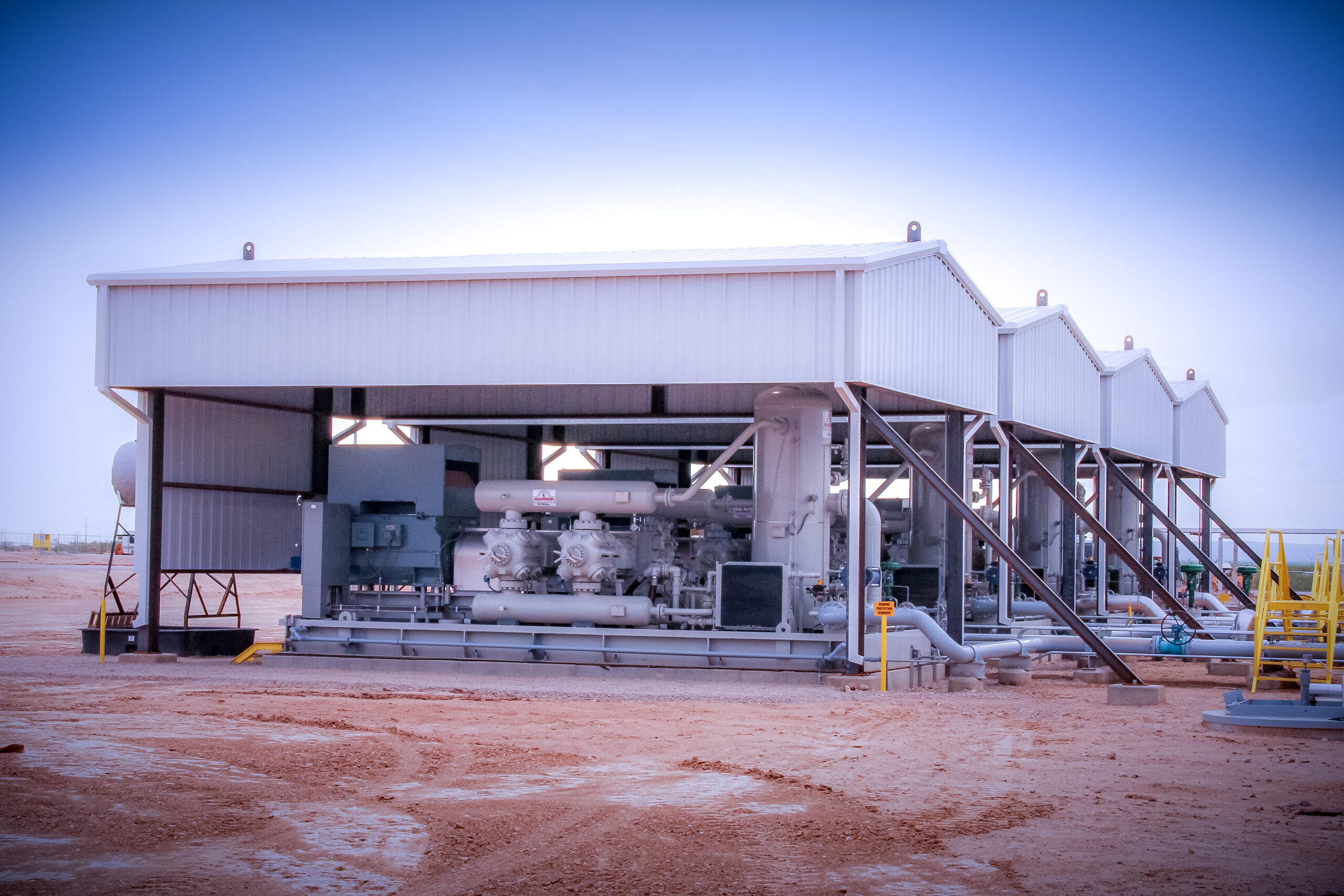
    CANUSA EPC’s execution model brings practical modularization to your project. Read more about some of our projects using modular approaches such as the Helium Multiwell Purification Battery or 50 MMSCFD Gas Compressor Station. 


    Technical Requirements for Qualifying CO₂-EOR Projects 

    According to the DOE’s CCUS Appendix H, projects must meet several technical criteria to qualify for the $85/ton credit: 

    • High-purity CO₂ supply (typically >95%) 
    • Compression systems capable of delivering CO₂ at 1,200–2,200 psi 
    • Reservoirs with sufficient porosity and caprock integrity 
    • EPA Class VI injection wells for geological storage 
    • MRV plans approved by the EPA or equivalent state authority 

    Developing a low-cost injection project requires selection of the proper dehydration approach for water-saturated CO2.  CANUSA EPC has released dehydration studies for CO2 projects, helping you select the correct technology for your CO2 project. 


    Strategic Recommendations for CO2 EOR Evaluations 

    • Determine Key Performance Metrics: Execute a FEED study to determine the proper metrics for financial investment; levelized cost per mton of CO2 product, carbon intensity to capture and process the CO2, and utility requirements. 
    • Leverage Modular EPC Execution: Accelerate lead times, improve cost control, and reduce compliance costs with modularized systems. 
    • Engage Tax Equity Partners Early: The $85/ton credit makes your project more bankable — capitalize on it. 
    • Audit Your CO₂ Source: Ensure your CO₂ stream meets purity and volume thresholds to qualify. 


    Conclusion 

    The One Big Beautiful Bill Act has solidified the opportunity landscape for CO₂-EOR projects. By extending the $85/ton 45Q credit to EOR with geological storage, it rewards projects that combine carbon mitigation with energy production. For developers ready to meet the technical and regulatory requirements, the path to profitability just got a lot clearer. 

    Table Changes For OBBB Act

    Ready to design a CO₂-EOR project that qualifies for $85/ton?
    Connect with us to explore FEED support, modular compression systems, and turnkey EPC execution tailored for carbon capture and EOR. 


    PAPER AUTHORS  

    Forrest Churchill 


    External Sources: 

    https://www.congress.gov/bill/119th-congress/house-bill/1/text

    https://www.epa.gov/uic/final-class-vi-guidance-documents

    https://energy.sustainability-directory.com/term/non-recourse-financing/ 

    https://www.energy.gov/sites/default/files/2022-10/CCUS-Appendix_H-030521.pdf  

    https://www.globalccsinstitute.com/news-media/latest-news/u-s-preserves-and-increases-45q-credit-in-one-big-beautiful-bill-act/  

  • Compression Systems Design for Increased Gathering System Availability

    Compression Systems Design for Increased Gathering System Availability

    Production Gas Gathering: Liquid Management Strategies for Compression Systems Design

    Safe and efficient compressor systems design for operations is more critical than ever in today’s competitive energy landscape. We see our clients focusing on increasing reliability and availability with their design by reducing site releases and shutdowns related to liquid management. Not only are they increasing their availability to serve their clients, but they are also reducing reporting and emission costs as well.

    Liquid management for compressor systems has become increasingly complex – balancing safety, emissions regulations, and operational efficiency isn’t always simple. If your current setup still relies on direct drainage to atmospheric tanks or outdated separation equipment, you may face added risks, product loss, or compliance challenges. In this article, we cover more efficient alternatives to traditional liquid handling methods that reduce emissions, add protection, and improve overall system performance.

    Directly Draining Slug Catcher Liquids to Atmospheric Tanks – Not Recommended

    CANUSA EPC does not recommend draining condensate directly from the slug catcher to atmospheric storage tanks. While these direct setups were once common practice, they inherently limit the ability to provide effective relief protection. The atmospheric tanks could be exposed to station inlet pressure in the event of a level control valve failure at the slug catcher, which is a risk that undermines the overall safety of the facility. This realization has driven us to incorporate design for liquid management that safeguards critical process equipment during unexpected failures.

    Enhancing Safety with Low Pressure Separators

    One innovative solution we have implemented is to use a Low Pressure (LP) Separator to manage liquids leaving the slug catcher. The LP Separator acts as an intermediate stopping point, preventing flow directly into atmospheric tanks. By degassing the slug catcher liquids in the LP Separator, the flash vapors are directed to a Vapor Recovery Unit (VRU), reducing methane emissions on the facility.

    This dual action:

    • Protects the tanks in the unlikely event of a control valve failure, and
    • Improves emissions reduction and enhances overall site reliability.

    How Vapor Recovery Units (VRUs) Reduce Methane Emissions in Compressor Stations

    Directing vapors from the LP Separator to the VRU plays a crucial role in improved VRU performance, thus reducing methane emissions. According to the EPA, Vapor Recovery Units are a proven method for capturing vented methane and reducing emissions from LP gas sources like compressor stations or storage tanks. This recovery supports environmental compliance, such as OOOO(b), and improves the overall efficiency by reducing product losses. In an industry where both safety and environmental stewardship are paramount, this strategy represents a win-win scenario for compressor station design.

    This is a practical solution that checks two important boxes at once in compressor station design:

    • Protecting your people and equipment, and
    • Keeping emissions in check.

    Overcoming Limitations of Coalescers with High Pressure Separation

    In addition to LP Separators, CANUSA EPC’s engineering approach advocates for the use of a High Pressure (HP) Separator downstream of gas compression, yet upstream of the coalescer. Coalescers are traditionally used for gas/liquid separation; however, they’re not ideally suited for separating hydrocarbon liquids from water. Liquids are more efficiently removed when incorporating an independent HP separator into the process. Through separating high-pressure hydrocarbon liquids from water before they reach the coalescer, the HP separator will provide value through three key aspects:

    1. Eliminates bulk liquid separation at coalescer
    2. Improves separation efficiency
    3. Extends the life of the coalescer

    Preventing Hydrate Formation in Drain Systems

    An important benefit of the HP Separator is its capacity to use separate drains for water and hydrocarbons. There is an increased risk of hydrate or ice formation when high-pressure fluids are discharged into a comingled line – this can cause costly blockages and potential safety incidents. The risk of hydrate formation is mitigated by directing water and hydrocarbon drain streams back to the inlet slug catcher via individual lines.

    Driving Industry Reliability and Best Practices

    The use of low-pressure and high-pressure separators in compressor stations represents the evolution of best practices for compressor systems and compressor station design. At CANUSA EPC, our designs incorporate integrated safety and efficiency best practices. By revising outdated practices, such as direct draining from slug catchers, we protect atmospheric storage tanks while improving liquid management and emissions reduction performance. These process engineering design principles enhance safety, reduce downtime, and decrease emissions in an increasingly cost-sensitive industry.

    Key Takeaways: Improving Compressor Station Design for Safer Liquid Management

    Innovation in compressor station design is vital for meeting today’s rigorous safety and environmental standards. Incorporation of LP and HP separators in compressor system designs demonstrates how thoughtful engineering can directly impact reliability, operational excellence, and environmental compliance.

    We look forward to exploring further advancements, from automated control systems to predictive maintenance technologies, that will shape the future of compressor station operations. As the oil and gas industry continues to evolve, the pursuit of smarter, more resilient designs will remain at the forefront of our efforts.

    PAPER AUTHORS: 

    Ted Zeiger, PE, Project Engineering Lead
    Connect on LinkedIn

    External Sources:

    https://www.epa.gov/natural-gas-star-program/vapor-recovery-units

  • Navigating CO2 Project Developments: A Guide for Investment Considerations

    Navigating CO2 Project Developments: A Guide for Investment Considerations

    The development of carbon capture, utilization, and storage (CCUS) projects presents unique opportunities and challenges for investment firms looking to deploy capital into the carbon capture space. CANUSA EPC, with its extensive experience in evaluating and developing carbon capture projects, offers valuable insights and strategies to navigate this complex landscape.

    Determining Your Levelized Cost of CO2

    Determining the internal rate of return requires accurate Capital Expenditures as well as Operational Expenditures to determine the levelized cost of capture and transport of the CO2.

    The CapEx for the facility encompasses the construction of the capture process to provide the CO2 product. A large portion of CO2 project equipment costs will be tied up in compression equipment. Typically, large compression systems are custom-fabricated and require specialized services that are not readily available. Instead, CANUSA EPC recommends deploying compression systems with smaller units in parallel designs. This solution is more likely to:

    • be readily available (compress schedule),
    • allow for efficient capacity modulation of the system,
    • provide efficient scalability for capacity, and
    • produce higher reliability for the project.

    The OpEx to run the facility is predominately based on power consumption. There are important strategies to ensure the facility runs efficiently and power costs are structured appropriately. VFDs and soft starts can be used in combination to lower demand spikes and electricity bills. Read more about electrical drive approaches.

    Technology Development for CO2 Capture

    Capturing CO2 from sources with higher concentrations of CO2 (greater than 8%) leads to lower separation costs and less energy consumption. High concentrations of CO2 present de-risked capture technology, as they can rely on traditional methods. Recent technological deployments for engine emission applications are trending towards $40 per metric ton of CO2. CANUSA EPC highlights that CO2 emissions from amine plants and ethanol facilities are relatively pure and can be economically delivered to pipeline or beverage grade specifications. Read a detailed case study: CO2 Injection & Amine Emissions Capture.

    Transportation: Best By Truck, Rail, or Pipeline?

    Transporting CO2 from the capture site can be done via truck, rail, or pipeline, similar to oil or bulk goods. Trucking is suitable for smaller projects, topping out around 150 metric tons per day (MTPD) due to logistical complexities. Rail applications are viable for projects approaching 400 MTPD when there is an existing train line near the facility. Pipelines are the most efficient way to transport large amounts of CO2 to hubs for injection or distribution to industrial users. CANUSA EPC advises focusing on injecting CO2 into saline reservoirs close to the emitter source in states with primacy over Class II injection wells, as these projects are quicker to approve1.

    What Government Incentives are Applicable to CO2 Capture?

    The long-term commercial use of CO2 as an emission removal tool is still developing. Government programs, such as those funded under the Inflation Reduction Act (IRA), support many active projects through reimbursement programs like 45Q or 45Z. CANUSA EPC emphasizes the importance of executing projects in a manner that meets IRA requirements to take advantage of these incentives. This approach provides flexibility to adapt to any changes in the program. Read more about rebates for your project.

    Approaching Carbon Developments Wisely

    To successfully navigate the complexities of CO2 project development, it’s crucial to consider:

    • developing a levelized cost of carbon that accounts for CapEx and OpEx,
    • leveraging reliable CO2 capture technologies,
    • optimizing transportation methods or remove them with onsite injection, and
    • capitalizing on government incentives.

    By implementing these strategies, investment firms can enhance the efficiency and profitability of their CO2 projects while contributing to a sustainable future.


    Let’s work together to help build a financial model for your CO2 project.  With just a few data points, we will provide a report that will bring clarity to your project’s feasibility – request a free Class V Estimate.


    Source: 1 https://www.epa.gov/uic/primary-enforcement-authority-underground-injection-control-program-0


  • CO2 Dehydration Study Reduces Project Risk: Injection

    CO2 Dehydration Study Reduces Project Risk: Injection

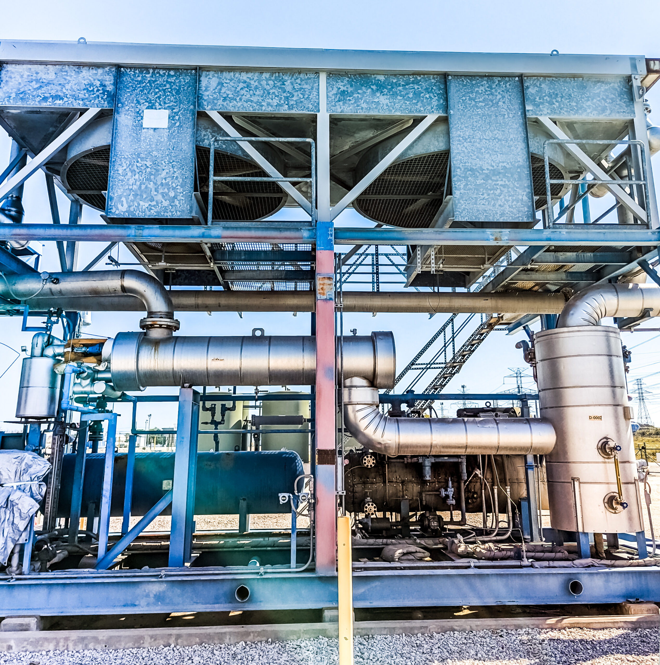
    Excess water in CO2 streams can lead to severe project risks, including equipment failure, blocked pipelines, and compromised system integrity. Without accurate data and a clear strategy, saturated CO2 can cause significant operating challenges. Technology selection during a CO2 injection project impacts profitability, safety, and longevity. A comprehensive CO2 dehydration study is the key to preventing these risks. It provides the clarity you need to make informed technology decisions, ensuring your operations remain safe, reliable and efficient.

    The Hidden Threat of Water in CO2 Streams

    Excess water in CO2 streams poses significant risks, including:

    • Pipeline Corrosion:

      Water reacts with CO2 to form carbonic acid, which can rapidly erode infrastructure.
    • Hydrate Formation:

      Under high-pressure conditions, water can crystallize, causing blockages that disrupt operations.
    • Reduced Injection Efficiency:

      High water content undermines injection reliability, leading to expensive maintenance and unplanned downtime.

    Water content targets typically range from 10 ppm to 50 lb/MMscf, depending on your transportation strategy, materials selection, and injection goals. For projects involving long pipelines or stringent injection requirements, managing water content isn’t optional—it’s essential.

    engineers reviewing dehydration study

    Why a Dehydration Study Is Your Vital First Step

    The right dehydration study transforms uncertainty into clarity. It will provide actionable insights to guide your project and give you confidence with decision-making.

    Here’s how:

    1. Define Project Objectives and Constraints:
      • Document your project’s goals, specifications, and concerns. A clear starting point ensures alignment across project teams.
    2. Understand the Composition of your Gas Stream:
      • Analyze the composition of your CO2 stream, identifying contaminants that may affect dehydration technology performance.
    3. Clear Evaluation of Dehydration Technology Options:
      • Compare technologies based on CapEx, OpEx, operability, and scalability. Focus on solutions that align with your team’s expertise and long-term project needs.
    4. A Transparent and Unbiased Analysis:
      • Selecting dehydration technology often involve trade-offs between cost, efficiency, and future expandability. A comprehensive study gives you the confidence to choose the right solution without surprises.

    Comparing CO2 Dehydration Technologies

    Selecting the right technology depends on your project’s specific needs. A breakdown of common options is below:

    • Glycol Absorption Dehydration using Tri-Ethylene Glycol (TEG):
      • One of the most common technology suitable for many projects.
      • Requires additional modifications to achieve ultra-low water content.
      • Larger footprint and higher maintenance demands.
    • Desiccant Adsorption Systems:
      • Achieves extremely low water content, ideal for stringent requirements.
      • Higher upfront costs due to desiccant materials.
      • Ideal for projects with ultra-low water content targets.
    • Semi-Permeable Membranes:
      • Advanced systems offering high efficiency.
      • Require gas pre-treatment and higher inlet pressures, increasing upfront investment.
      • Ideal for projects needing minimal removal.
    • Chiller/Refrigeration Systems:
      • Uses dew point control to condense water from the vapor phase to a liquid.
      • Options like DEXPro leverage innovative solutions for energy-efficient cooling.
      • Effective for moderate water removal but with limitations on extreme requirements.

    * Detailed characteristics have been compiled for each of these technologies and are available for review by downloading the full dehydration paper.

    oil and gas dehydration equipment

    Real-World Success: Evaluation Findings for CO2 Dehydration

    In a recent CO2 injection project, CANUSA EPC was asked to evaluate dehydration options for reducing water to a 25 lb limit in the gas stream prior to injection.

    The framework of their evaluation can be considered a minimum viable standard for dehydration analysis.

    • Reliability
    • Uptime
    • CapEx and OpEx
    • Safety
    • Schedule Risk
    • Operability/Ease of Maintenance
    • Stakeholder Support
    • Environmental Impact
    • Expansion Potential

    The following dehydration solutions were evaluated to determine which technology would best meet the client’s requirements:

    • Traditional TEG
    • Chiller Package
    • Integrated DEXPro solution

    The result?

    *A detailed comparison table is available for review by downloading the full dehydration paper.

    In this client’s case, DEXPro stood out for its integration capabilities, environmental efficiency, and alignment with the client’s sustainability goals.

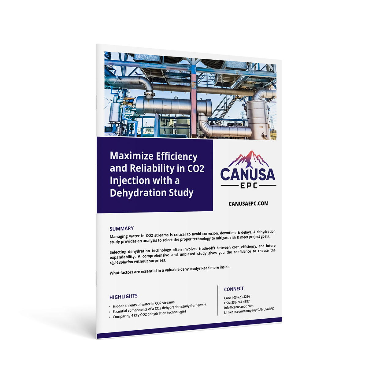
    Download the Full Paper on CO2 Injection & Dehydration:

    Access the comparison of key technologies presented in this article by downloading CANUSA EPC’s paper.

    Click here to download: Maximize Efficiency & Reliability in CO2 Injection

    Embarking on a CO2 injection project without a dehydration study is like flying blind. Start with this critical step and ensure the dehydration study follows the framework within the paper – before assembling your project team.

    PAPER AUTHORS: 
    Tevin Champagne, Project Manager
    Connect on LinkedIn

    Josh Hoeft, Project Manager
    Connect on LinkedIn

    Nick Brown, Project Engineer
    Connect on LinkedIn

    Ted Zeiger, PE,  Project Engineering Lead
    Connect on LinkedIn


  • Repurposing Oil & Gas Equipment: A Cost-Effective Solution?

    Repurposing Oil & Gas Equipment: A Cost-Effective Solution?

    Energy projects face shrinking budgets and tighter timelines. Operators, together with their engineering teams, are challenged to find creative cost-reduction solutions without compromising safety or performance.  

    Reusing, relocating, and repurposing oil and gas equipment, is a popular strategy for its cost-effectiveness. Whether placing existing separators into new services or relocating gas compressors and refrigeration units to new fields, this approach can help you meet deadlines and budget constraints. 

    There are many reasons to explore this strategy; however, ‘proceed with caution’ is our overarching advice. There may be instances in which new equipment is still the more reliable and effective solution. 
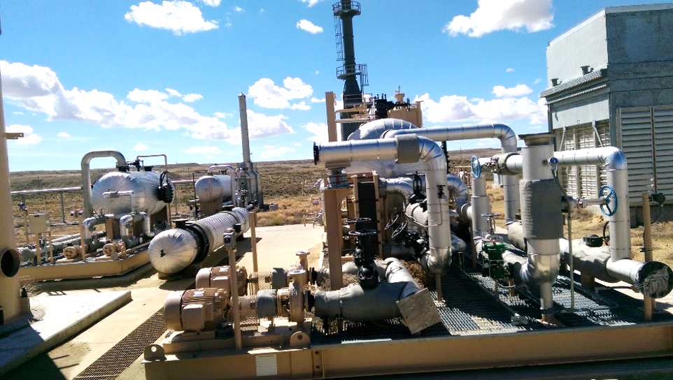
    used equipment on skid

    Benefits of Repurposing Oil and Gas Equipment?

    • Cost Savings:
      Leveraging existing assets can reduce capital expenditure.  This cost savings though if often reduced after include inspection and modification scope for repurposing the equipment.
       
    • Time Efficiency:
      Reused equipment, when available and functional, can often be deployed more quickly than waiting for new orders.
       
    • Sustainability:
      Repurposing equipment aligns with corporate sustainability goals by reducing waste and extending the lifecycle of assets.
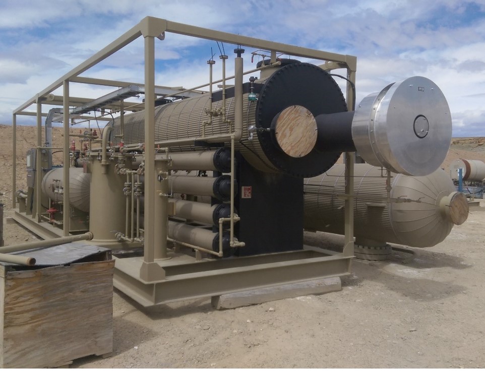


    direct fired stabilizer skid

    Key Considerations for Reusing Equipment 

    Governing Codes and Standards
    When repurposing oil and gas equipment, it’s crucial to follow applicable industry standards to ensure safety and performance.  These are some of the most relevant codes: 

    • API 510: Pressure Vessel Inspection Code 
    • API RP 572: Inspection Practices for Pressure Vessels 
    • API 570: Piping Inspection Code 
    • API RP 576: Inspection of Pressure-Relieving Devices 
    • API STD 653: Tank Inspection, Repair, Alteration, and Reconstruction 
    • API STD 579: Fitness-for-Service 

    Compliance with these standards ensures that reused equipment can be safely integrated into new operations. 

    API | Purchase API Standards & Software


    ASME
    In addition to API codes, several other standards must be adhered to, depending on the jurisdiction and specific industry requirements. Organizations must follow all application health and safety regulations.  


    CODES/STANDARDS FOR REUSING EQUIPMENT IN CANADA

    CSA Standards (Canadian Standards Association): 

    • CSA B51: Boiler, Pressure Vessel, and Pressure Piping Code: Governs the construction, installation, inspection, and certification of pressure vessels and piping systems across Canada. 
    • CSA Z662: Oil and Gas Pipeline Systems: Governs the design, construction, operation, and maintenance of pipeline systems in Canada. It’s essential for any relocation or repurposing of gas pipelines and similar systems. 
    • CSA W59: Welded Steel Construction: This is relevant for any welding work needed in repurposing or relocating equipment. 

    Provincial and Territorial Regulations: 

    • Each Canadian province and territory havs its own regulatory body that oversees pressure vessels and related equipment. For example, ABSA (Alberta Boiler Safety Association) in Alberta regulates pressure equipment safety in the province. 


    CODES/STANDARDS FOR REUSING EQUIPMENT IN THE USA

    ASME (American Society of Mechanical Engineers) Codes 

    • ASME Section VIII: Rules for Construction of Pressure Vessels: This code is widely used across the United States and is also accepted in Canada. 
    • ASME B31.3: Process Piping: This applies to piping used in chemical, petroleum, and related industries. 

    National Board Inspection Code (NBIC)

    • A key standard in the United States for the inspection, repair, and alteration of pressure vessels and boilers. 


    CROSS-BORDER COMPATIBILITY

    If equipment is being relocated across borders (e.g., from the U.S. to Canada or vice versa or state-to-state), it’s important to ensure that the equipment complies with the local regulatory standards in the new jurisdiction. 
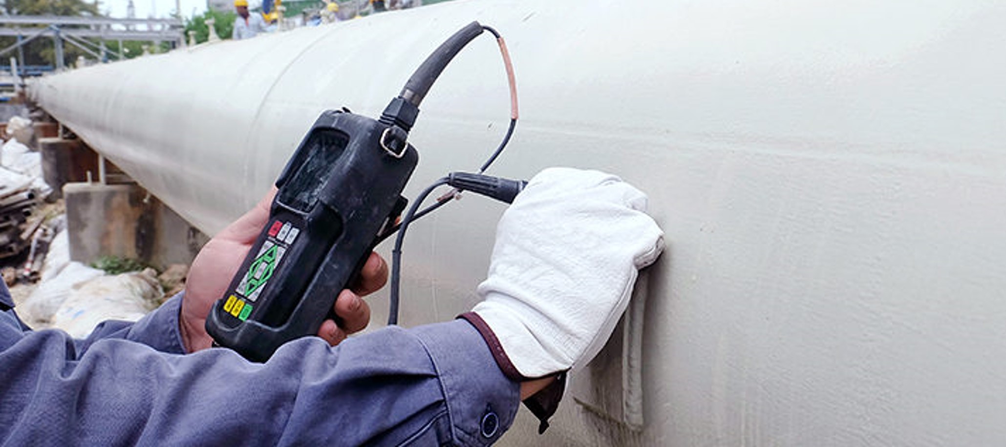
     

    hand and monitoring device inspecting used equipment

    Inspection Requirements 

    Before deploying any equipment into new service, a thorough inspection is necessary. A detailed inspection plan should be developed based on the equipment’s condition, service history, and the specific requirements of the new application. 

    Key Inspection Elements: 

    • Service History: Understanding the previous operational conditions is critical. Identify signs of corrosion, cracking, blistering, and other types of degradation. Key factors include material thickness, the presence of under-insulation corrosion, and dimensional changes. 
    • Non-Destructive Examination (NDE): Depending on the equipment’s condition, this may include ultrasonic thickness measurements, radiographic inspections, and magnetic particle testing. 
    • Confined Space Entry Requirements: Ensure proper safety protocols are in place, as many inspections may require confined space entry. 
    • Documentation Review: It’s critical to review previous drawings, inspection records, and any reports related to modifications, damage, or repairs. 
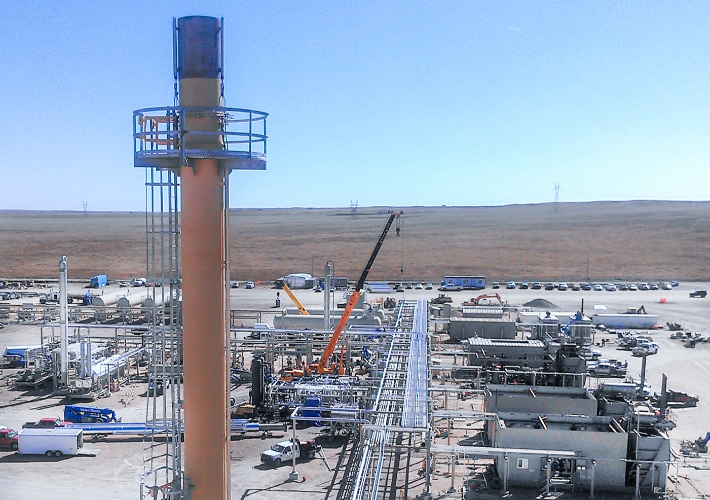
     

    birds eye view of oil and gas site

    Challenges in Documentation and Material Verification 

    Lack of proper documentation (e.g., missing original equipment drawings or insufficient inspection records) is a significant red flag.  

    For pressure vessels, the ASME Code Section VIII, Division I, UG-10(c) provides guidance for handling unknown materials, but it may lead to conservative assumptions, such as reducing the maximum allowable stress and working pressure. 

    For cryogenic skids, ASME B31.3 (Process Piping) and Section VIII, Division I provide guidance on material selection and stress analysis. When dealing with unknown materials in cryogenic service, you must perform material verification, including testing for low-temperature toughness. If material properties cannot be confirmed, conservative assumptions such as derating the design temperature and applying a lower allowable stress may be necessary, potentially impacting the overall performance and safety of the skid in cryogenic applications. 
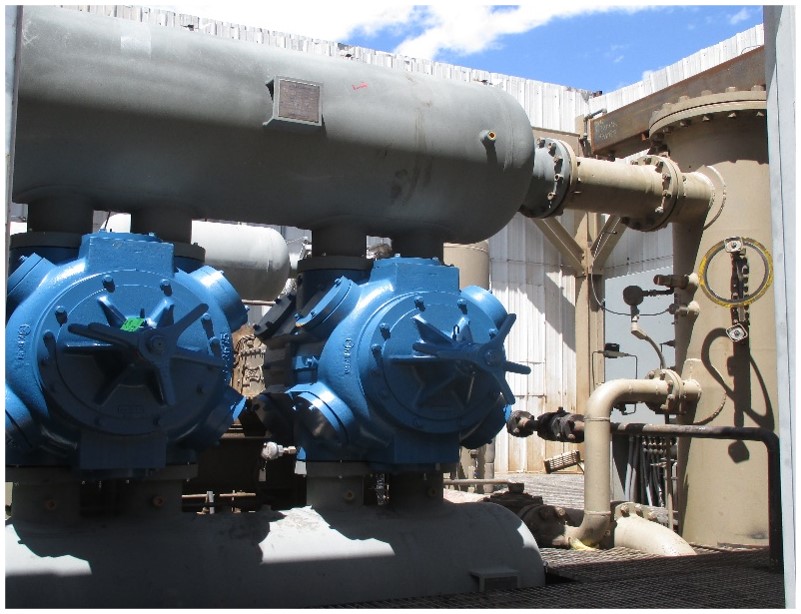
     

    Case Example: When Re-purposing Costs More 

    While repurposing equipment can lead to savings, without the proper pre-evaluation, there is great risk that it could have the opposite effect.  

    Consider a 5,000 bpd stabilizer skid package with an on-skid direct-fired reboiler.  

    Overseen safety concerns necessitate replacing the burner fire tube with a custom electric heater. This modification incurred costs that exceeded the procurement of a traditional reboiler unit. Additionally, shop installation delays pushed the project past the lead time for new equipment. 
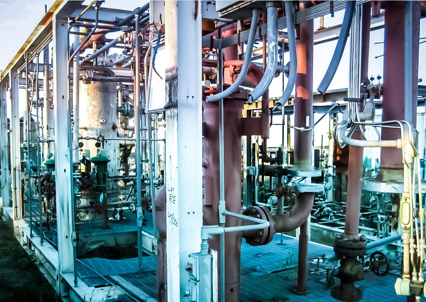
     

    equipment on cryogenic skid

    Is Reused Equipment Always Faster and Cheaper? 

    The benefits of reusing equipment must be weighed against potential downsides, such as: 

    • Modifications that are more expensive than anticipated. 
    • Delays caused by unforeseen repair or upgrade needs. 
    • Documentation issues that result in excessive safety factors and reduced efficiency. 

    In some cases, especially with high-pressure equipment, the savings from repurposing can be significant. However, lower-pressure systems may not justify the additional effort, and purchasing new equipment might be the more cost-effective solution in the long run. 
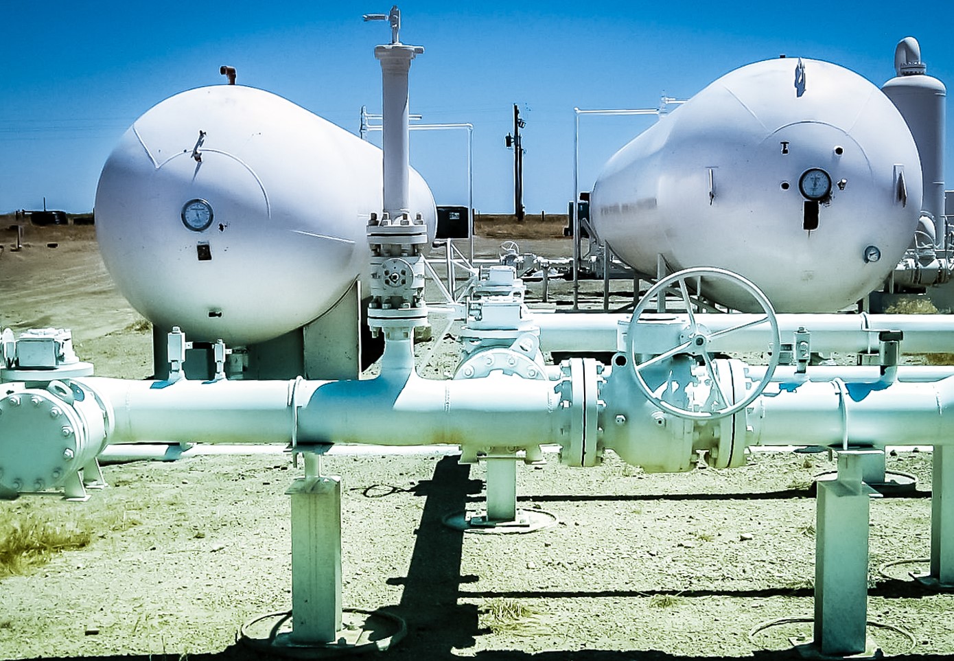
     

    bullet vessels on oil and gas site

    How to Be Sure: Inspections for Assessing the Viability of Used Equipment 

    While reusing equipment has clear advantages, in some cases, new equipment may still be the more reliable and effective solution.  

    Your engineering team must be able to clearly identify the risks and rewards of deploying used equipment. A thorough inspection and documentation verification will empower you to make informed decisions about equipment use, while balancing cost, time, and safety. 

    Consider: 

    • Involvement of Engineering Early On:
      Involving engineers in the evaluation process can identify potential risks and help determine whether the repurposed equipment will meet operational requirements.
       
    • Transparent and Clear Documentation/Inspection Findings:
      Without these, the project could face significant delays and/or incur higher costs.
       
    • Creative Solutions:
      Sometimes, existing equipment needs only minor adjustments to function in a new service. These modifications must be balanced against the cost and time of new equipment procurement.


    If you have access to used equipment and are curious of the potential savings – connect with us.
    It is vital to properly assess the risks and rewards!