Expertise: Emissions Reduction

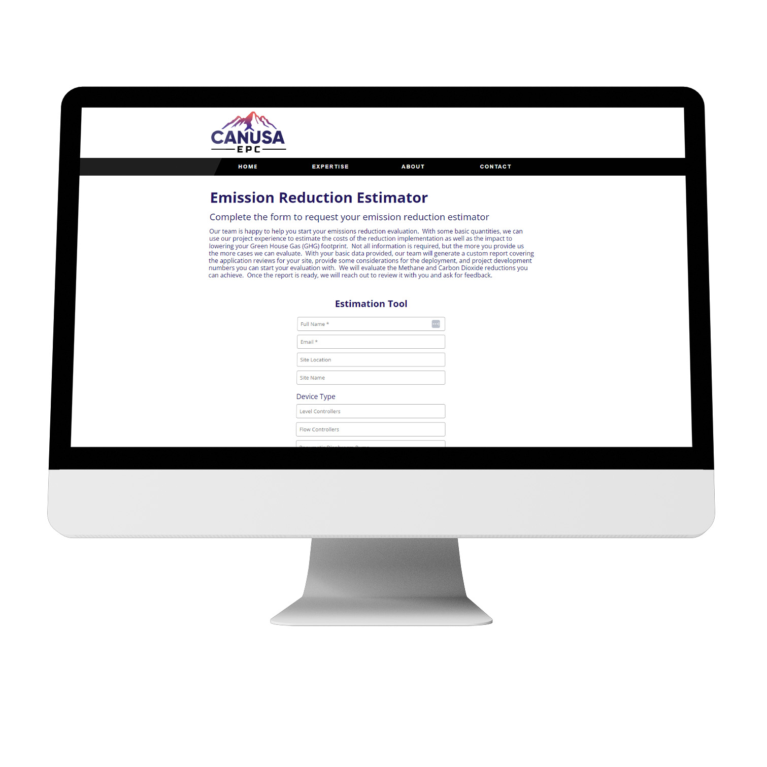
  • Emission Reduction Estimator

    Emission Reduction Estimator

    Summary

    Develop a basis for the evaluation of your emissions reduction efforts in your sites. With some basic quantities, we can use our project experience to estimate the costs of the reduction implementation as well as the impact of lowering your Green House Gas (GHG) footprint.

  • LNG: Market Drivers & Technology Spotlight

    LNG: Market Drivers & Technology Spotlight

    Global energy demand is on the rise and LNG facilities are playing a bigger role than ever. LNG is a flexible, lower-emission fuel, and a way to transport and trade natural gas that was once landlocked by domestic demand. Natural gas demand is expected to grow 32% by 2050 with no peak in sight. This massive growth is driven by: 

    • Artificial intelligence 
    • Switch fuel  
    • Backup fuel, and 
    • Transport fuel. 

    Kindra Snow-McGregor, PE, from PetroSkills delivered a technical presentation for the WOGA (Women in Oil and Gas Association) April Technical Luncheon – “LNG Market Drivers & Technology”. Lila Salley attended and in this article she shares her key takeaways. 

    The North American market is rushing to build out LNG infrastructure, as shown in the figure below, to capture more of the international demand and there are numerous challenges. Understanding the market and project development landscape is critical if you want your LNG plans to run smoothly — and profitably.  

    Figure 1: Existing and under construction LNG facilities in North America (2016-2028) 

    Lila breaks down what Kindra shared about the current market considerations. 

    What is LNG and Why It Matters 

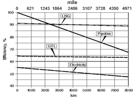
    LNG is natural gas cooled to -260°F to become a liquid, reducing its volume and then shipped at atmospheric pressure. This makes it far more efficient to store and transport — especially over long distances. In fact, LNG is more transportation-efficient than pipeline gas for distances over 1,500 miles and maintains its efficiency even up to 8,000 miles.  

    LNG Nominal Gas Transportation  

    Figure 2: Nominal natural gas transportation efficiency 

    LNG’s uses span across: 

    • Power generation and heating 
    • Transportation fuel 
    • Industrial heat source 
    • Chemical feedstock 

    LNG is emerging and North America is playing catch-up fast.  

    • We are projected to double LNG exports by 2028 
    • US produces 26% of international natural gas consumption demand 
    • 64% of US LNG exports went to Europe in 2024 

    LNG Liquefaction Facilities 

    The LNG market is hot, but that doesn’t make execution easy. Here are some of the biggest hurdles operators face today.

    1. LNG Facility Costs & Scale are Staggering

    Liquefaction facilities are capital-heavy: $1 billion per 1 million tonnes per year (mtpy) of capacity is the norm. A 5 mtpy plant, a mid-size operation, needs: 

    • 715 MMscfd of feed gas 
    • 302,000 horsepower in electricity 
    • 150 fin fan air-cooled exchangers 

    That’s before you factor in the 7–8% of gas burned internally just to run the plant.  

    Operator challenge: Building at scale while maintaining fuel efficiency and hitting commercial milestones. 

    2. Feed Gas Quality is a Hidden Risk 

    LNG specs are tight — especially around acid gas and mercury content. Many upstream sources don’t meet this standard without significant pretreatment. 

    Operator challenge: Designing flexible front-end systems to handle varying feedstock quality without ballooning costs. 

    3. US LNG Trading Long-Term vs. Spot Market 

    • Fixed fee of $2.25-3.50 per MMBtu is paid irrespective of lifted volume 
    • Shipping and re-gasification costs are covered by the buyer 
    • Trading driven by margin between Henry Hub price and regional spot market

    Operator challenge: Balancing long-term fixed fee structures with market uncertainty. 

    4. Technology Choice Can Make or Break ROI 

    • ConocoPhillips Optimized Cascade® is a process that utilizes pure propane, ethylene, and methane as refrigerants in a three-stage closed loop circuit. A heavies removal unit (HRU) and/or a nitrogen rejection unit (NRU) can be added to the LNG train depending on the feed composition and downstream requirements.  
    • APCI-C3MR includes a pre-treatment train to sweeten, dehydrate, and pre-cool the feed gas. Four stages of propane chilling are used to cool the mixed refrigerant which then enters a cryogenic heat exchanger to liquefy the pre-treated gas stream. 
    • Chart IPSMR™ technology utilizes a heavy hydrocarbon removal system to remove freezing components from the feed gas before liquefaction.  A single mixed refrigerant and a cold box comprised of brazed aluminum heat exchangers are then used to liquify the pre-treated gas stream.  

    Each has trade-offs in footprint, energy intensity, and startup cost. Choosing the wrong one can delay timelines or limit flexibility later.  

    If you are curious and would like to discuss these, connect with us. 

    Operator challenge: Matching process technology to project goals, gas characteristics, and long-term offtake strategy. 

    5. LNG Storage and Shipping 

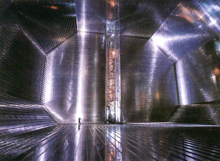
    LNG fuelled vessels produce 23% less greenhouse gases. The typical LNG carrier size is 175,000m3, the scale of which can be seen in Figure 3 below. It’s cargo values between $21 to $39 million FOB. 

    Figure 3: LNG is pumped directly into the interior of the double hulled carrier for shipment. 

    Marine transport requires specialized LNG carriers, and receiving terminals must have the infrastructure for regasification, storage, and delivery. On land, LNG Virtual Pipelines are increasingly being used for off-grid power generation, truck refueling stations, and supplying gas to remote communities — all requiring small-scale storage hubs and flexible distribution networks. 

    Operator challenge: Designing for both large-scale export and decentralized delivery. As LNG applications diversify, infrastructure must be adaptable, scalable, and aligned with local demand — without driving up costs or complexity.

    6. European ESG Standards 

    The EU Methane Regulation was updated in August of 2024 and applies to both new and existing LNG supply contracts.  

    Importers are now required to submit details on methane measurement, reporting, and verification (MRV) methodologies from both the exporter and the producer, as well as methane intensity data. Importers must also take “all reasonable efforts” to ensure the MRV measures at the level of the producer are equivalent to those defined by the EU Methane Regulation.  

    Operator challenge: In the United States market, the importer often does not have a direct contractual relationship with the producer. It is important to be aware of this complexity in order to comply with the reporting requirements.  

    LNG Outlook for 2025 

    LNG operators who succeed will be the ones who design for variability, build for efficiency, and plan for volatility. 

    Kindra referenced the Shell LNG Outlook for 2025. It is a current resource with various tools for you to learn more about the current state of LNG – in-depth report, key facts and figures video, infographics and more.  

    The team at CANUSA found Kindra’s PetroSkills presentation incredibly valuable and extend appreciation to WOGA for hosting the event.  

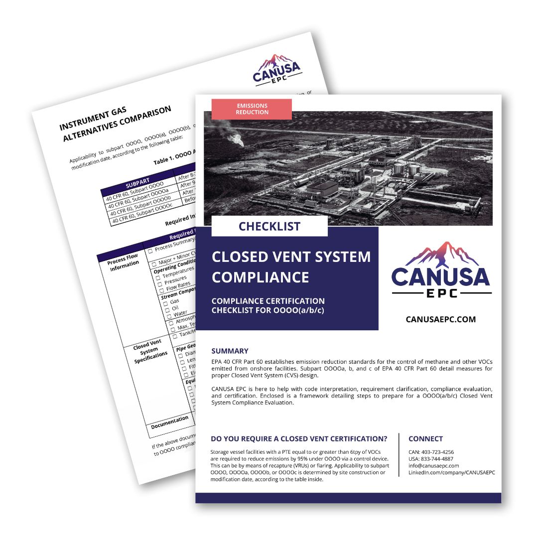
  • Closed Vent System Compliance Certification Checklist For OOOO(a/b/c)

    Closed Vent System Compliance Certification Checklist For OOOO(a/b/c)

    Summary

    EPA 40 CFR Part 60 establishes emission reduction standards for the control of methane and other VOCs emitted from onshore facilities. Subpart OOOO(a/b/c) of EPA 40 CFR Part 60 detail measures for proper Closed Vent System (CVS) design.

    CANUSA EPC is here to help with code interpretation, requirement clarification, compliance evaluation, and certification. Enclosed is a framework detailing steps to prepare for a OOOO(a/b/c) Closed Vent System Compliance Evaluation.

    This guide includes:

    • Applicability Dates
    • Process Flow Information
    • Closed Vent System Specifications
    • Documentation
  • Instrument Air, Nitrogen, or Electric? A Side-by-Side Look at Instrumentation Alternatives for Emissions Reduction Compliance

    Instrument Air, Nitrogen, or Electric? A Side-by-Side Look at Instrumentation Alternatives for Emissions Reduction Compliance

    As the Oil & Gas industry adapts to new environmental standards introduced through the EPA regulation OOOOb, operators are looking for low-emission substitutes for traditional instrument gas systems for pneumatic devices. Factors like power availability, extreme climates, retrofit feasibility, and long-term operating costs influence the most economical and technically viable instrument gas alternatives factor into the decision. 

    Although instrument air is a popular choice for pneumatic devices, there are a variety of instrument gas alternatives that are worth considering. These options include using liquid nitrogen tanks to supply gas to pneumatic devices, using electric actuators on valves, using a combustion-based or compressor-based vent capture system, and implementing low-emission alternatives to traditional pneumatic devices. 


    Controlling Instrument Gas Emissions 

    Natural gas-driven pneumatic devices have been the standard across upstream and midstream oil and gas sites for decades. These systems are simple, reliable, and easy to integrate, but they are a significant source of methane and VOC emissions in the oil and gas industry.  

    In the U.S., regulatory frameworks like EPA “OOOOb” (and soon, “OOOOc”) have required the transition away from traditional instrument gas systems. EPA Subpart OOOOb section 60.5390b requires operators to “design and operate each process controller affected facility with zero methane and VOC emissions to the atmosphere”, beginning January 22, 2027. The regulation includes mandatory monitoring and reporting for all facilities.    

    In Canada, producers are adopting emissions reduction strategies to align with both internal and external ESG targets, investor expectations, and net-zero commitments. 

    Controlling instrument gas emissions by implementing low-emission alternatives is the future of the industry.  

    The challenge? Each instrument gas alternative comes with its own trade-offs. Let’s evaluate! 


    Key Considerations 

    These three considerations often stall progress or lead to overbuilt systems that don’t actually meet site needs. These are the top 3 we see: 

    1. Site Limitations

      Power availability, space constraints, and environmental conditions will determine what is feasible.
    2. Budgeting & ROI

      Every solution requires both CAPEX & OPEX. Liquid nitrogen systems, while low in initial cost, come with recurring delivery fees. Electric actuators are expensive, power-intensive, and, on existing sites, require retrofitting of every actuated valve.
    3. Technology Trade-offs

      Each alternative has a unique set of pros and cons. Some offer zero emissions but require significant upfront investment. Others are easier to implement but come with ongoing operational costs or limited scalability.


    Comparing the Top Alternatives for Traditional Instrument Gas Systems  

    Instrument Air Systems

    Instrument air is one of the most established alternatives to gas-driven pneumatics, particularly in midstream facilities. These systems use electric-driven compressors to deliver clean, dry air to valves and controllers, eliminating methane emissions entirely. 

    Pros: 

    • Easy integration  
    • Eliminates all process controller emissions – OOOO(b) compliant with no continued reporting 
    • Compatible with most existing pneumatic devices 
    • Product saved – no longer using sales gas to operate pneumatic devices 
    • Air is non-corrosive and abundant 
    • Expandable to pneumatic pumps and other emission reduction efforts (i.e. start air) 

    Cons: 

    • Introduces an additional piece of rotating equipment 
    • Requires power and space for compressors and dryers 
    • Higher upfront capital costs 
    • Possible rework of existing piping  
    • Introduces an oxidizer into pneumatic lines 
    • Increased operational effort due to required maintenance and troubleshooting 

    Best for: Midstream or central facilities with power availability.

    Vendors Offering Compression: UECompression Packages 

    • 5 HP or 15 HP Reciprocating Packages 
    • Duplex Recip. Package 
    • 5 HP Rotary Scroll  
    • Custom Packages 


    Liquid Nitrogen Supply Systems 

    An option for remote or off-grid sites, liquid nitrogen provides a zero-emission, power-free alternative for driving pneumatic equipment. Suppliers deliver nitrogen in pressurized vessels, and nitrogen is passed through regulators to send vaporized nitrogen to drive pneumatic devices. 

    Pros: 

    • Easy integration 
    • Eliminates all process controller emissions – OOOO(b) compliant with no additional reporting 
    • Product saved – no longer using sales gas to operate pneumatic devices 
    • Pros over air – no additional rotating equipment 
    • Pros over gas – removes requirements for reporting to the EPA 
    • N2 is inert and does not provide an oxidizer into the process 
    • No additional power requirements 
    • Easily scalable & reliable  
    • No upfront capex requirements 
    • Minimal operator involvement 
    • Minimal seasonal, weather, or temperature implications 

    Cons: 

    • Requires regular nitrogen delivery (every 30–60 days) – adds to OPEX, delivery scheduling, risk of delays/impact to schedule 
    • Safety concerns with the addition of a pressurized vessel 
    • Not yet widely used, may face internal approval challenges 

    Best for: Small well pads or facilities without power infrastructure.

    Vendors Offering Liquid Nitrogen Systems: Kathairos Solutions  

    • Provides services through the full timeline for integration, from site assessment to commissioning, monitoring, reporting, and operation. 


    Electric Valve Actuators 

    Electric actuators provide an emissions-free solution to control valve actuation, eliminating the need for access to pneumatic supply lines. They’re ideal for on/off valves in remote pipeline applications. 

    Pros: 

    • Emission-free 
    • Self-calibrating 
    • Low energy requirement 
    • Can be used in low temperature operation 
    • No need for routing of pneumatic lines 
    • Remote monitoring and configuration are available 
    • Solar-powered options are available – remote, power-free pipeline applications 

    Cons: 

    • Significant upfront capex – not realistic for large facilities with many actuated valves 
    • Slow response time – not suitable for tight process control 
    • Not suitable or realistic for existing facilities – requires significant modification to existing valves 
    • May not eliminate the need for pneumatic systems; other pneumatic signal users may exist apart from control valves 
    • Limited applicability as an emissions reduction technology in industry  
    • New technology – lack of familiarity or approval with clients and operators 
    • Although additional energy requirement and cable routing.  
    • Cannot operate on loss of power 

     Best for: Remote oil and gas sites with few pneumatic valves, and no additional pneumatic users. 

    Vendors Offering Electric Actuation: Emerson  

    • Varied applications suited for shut-down valves and control valves.  
    • Offering range of sizes and duty cycles. 


    Combustion-Based Vent Gas Capture 

    This strategy captures emissions from gas-driven pneumatics and routes them to a combustor, converting natural gas into CO₂. Although this method requires continued reporting with the EPA, it can offer OOOOb compliance with minimal disruption in operations.

    Pros: 

    • Can continue to use instrument gas, no need to modify existing piping 
    • Eliminates need for additional rotating equipment, leading to equipment and operational savings 
    • Low initial Capex (if combustor is existing on site) 
    • No additional power requirements 
    • Possible tank battery applications – routing captured pneumatic emissions to tank venting header 

    Cons: 

    • Requires design and installation of a cover that can capture emissions from existing equipment 
    • Only realistic if there is an existing combustor that captured emissions can be routed to 
    • Significant engineering and design time 
    • Does not fully eliminate emissions from pneumatic devices. Monitoring and reporting are still required for OOOO(b) compliance 

    Best for: Facilities with an existing combustor and limited resources for a full system overhaul.


    Capturing Compressor Emissions for Instrument Gas Use 

    This approach captures small amounts of vented gas from compressors and reuses it to power pneumatic devices. It’s a creative way to minimize waste and emissions using existing infrastructure. 

    Pros: 

    • Reduces total emissions from compressors 
    • Removes the need for header routing to compressors 
    • No additional power requirements 
    • Marginal increase in sales of gas 
    • OOOO(b) compliance for compressor emissions capture and process controllers 

    Cons: 

    • Significant engineering and design time, modification of on-skid piping 
    • Does not fully eliminate emissions from pneumatic devices. Monitoring and reporting are still required for OOOO(b) compliance. 

    Best for: Sites looking to improve compressor efficiency or reduce emissions without installing new systems. 


    Which Pneumatic Emissions Reduction Technology is Best?  

    There are numerous technologies available to reduce or eliminate emissions from instrument gas lines, whether it be implementing solutions within an existing instrument gas system, adopting instrument air or vaporized nitrogen, or utilizing electrically actuated valves. Although instrument air has been the most widely used pneumatic signal alternative within the industry, operators should understand that other technologies exist and may be a more practical solution for eliminating instrument gas emissions. 

    The technologies available allow for flexibility in a wide range of applications. There are options for sites with limited power availability, existing facilities looking to retrofit or upgrade their traditional instrument gas system, remote pipeline operations, and new facilities looking to build out with an emissions-free pneumatic system.  

    At CANUSA EPC, we help operators make informed decisions based on real-world experience. We’ve seen the nuances of site power, valve density, weather risk, and regulatory targets. 

    When you’re ready to talk instrumentation upgrades or emissions strategies, we’d be happy to share what’s working in the field.  

    __________ 

    FURTHER EMISSIONS-REDUCTION READING  

    Instrument Gas Alternatives Comparison Guide
    To accompany this blog, we have created a free comparison guide for your convenience. Download the Instrument Gas Alternatives Comparison Guide.

    OOOO(b) for Compression Sites: Cost-Management Strategies for Methane Reduction
    Want to ensure you meet budget and timelines? Read on for 7 strategies to consider.
    __________ 

    Author(s) 

    Megan Hurley, Engineer I 

    External Sources 

    1. https://www.epa.gov/natural-gas-star-program/rulemakings-policy-and-laws-address-methane-emissions-oil-and-gas-sector#:~:text=Methane%20Emissions%20Standards,-Final%20Rules%20to&text=In%202024%2C%20EPA%20issued%20a,methane%20emissions%20from%20existing%20sources.&text=In%202016%20%2D%20EPA%20issued%20three,permitting%20requirements%20for%20the%20industry
    2. eCFR :: 40 CFR Part 60 Subpart OOOOb — Standards of Performance for Crude Oil and Natural Gas Facilities for Which Construction, Modification or Reconstruction Commenced After December 6, 2022  
    3. https://www.canada.ca/en/services/environment/weather/climatechange/climate-plan/2035-emissions-reduction-target.html 
  • Importing Industrial Equipment into Alberta: Pressure Vessel and Piping Compliance Explained

    Importing Industrial Equipment into Alberta: Pressure Vessel and Piping Compliance Explained

    Introduction

    Importing industrial equipment into Alberta is not as simple as crossing the border. Alberta regulates pressure vessels, pressure piping, and related systems at the provincial level through the Alberta Boilers Safety Association (ABSA), creating unique requirements for owners, EPCs, and equipment suppliers.

    Failure to address these requirements early—especially when importing used or surplus equipment—can result in customs delays, rejected equipment, forced retrofits, or extended commissioning timelines. This article outlines the key regulatory requirements governing pressure equipment in Alberta and explains how proactive compliance planning reduces project risk.

    1. ABSA Jurisdiction and Pressure Equipment Regulation

    Pressure equipment in Alberta is governed under the Pressure Equipment Safety Regulation (PESR), administered by the Alberta Boilers Safety Association (ABSA). ABSA is responsible for ensuring the safe design, construction, installation, and operation of pressure vessels, pressure piping, boilers, and fittings.

    More information on ABSA’s role and authority can be found at:
    https://www.absa.ca

    1. Pressure Vessel Requirements for Imported Equipment

    Pressure vessels imported into Alberta must comply with ASME Section VIII and be formally registered with ABSA prior to installation.

    Key requirements include:

    • Canadian Registration Number (CRN)
    • P.Eng-stamped design calculations
    • Manufacturer’s Data Reports
    • ABSA-recognized fabrication and inspection records
    • Material traceability and NDE documentation

    Used pressure vessels often require additional engineering review to validate original design conditions, service history, and suitability for continued operation.

    1. Pressure Piping Design Registration

    Pressure piping systems require formal design registration with ABSA, regardless of where fabrication occurs.

    Commonly applied codes include:

    • ASME B31.3 – Process Piping
    • CSA Z662 – Oil and Gas Pipeline Systems

    Design submissions typically include P&IDs, line designation tables, piping specifications, stress analysis (where required), and P.Eng-stamped documentation.

    ABSA guidance on piping design registration is available at:
    https://www.absa.ca/registration/pressure-piping

    1. Quality Management and Fabrication Controls

    Manufacturers and contractors may be required to maintain an ABSA-registered Quality Management System (AQP) to fabricate or assemble pressure equipment for use in Alberta.

    These systems govern welding procedures, welder qualifications, NDE, pressure testing, document control, and material traceability. Details on ABSA quality programs can be found at:
    https://www.absa.ca/quality-management

    1. Electrical and Structural Compliance

    Pressure equipment compliance must be coordinated with electrical and structural requirements.

    Electrical systems must comply with:

    • Canadian Electrical Code (CSA C22.1)
    • CSA or UL-C certified components
    • P.Eng-stamped electrical drawings

    Structural systems must meet:

    • Provincial building code requirements
    • CSA W59 welding standards
    • Site-specific wind and snow load criteria
    1. Special Considerations for Used and Surplus Equipment

    Used equipment introduces additional risk due to incomplete documentation, unknown modification history, and outdated codes of construction. Alberta regulators frequently require engineering assessments or re-registration before acceptance.

    CANUSA EPC has executed multiple projects involving reused equipment, including the NGL Fractionation Train Project, where previously utilized process equipment was integrated into a new fractionation facility while meeting Alberta pressure equipment and ABSA regulatory requirements:
    NGL Fractionation Train

    Similarly, the Expandable Gas Treatment Facility Project demonstrates how phased facility development and redeployed equipment can be successfully executed when regulatory compliance is addressed early in the design process:
    Expandable Gas Treatment Facility

    For additional insight into the regulatory challenges associated with used equipment, view our Used Equipment Webinar:
    https://youtu.be/u26kI4QzzvQ?si=yQ1Hrxwhs5By6LTo

    1. Why Compliance Before Shipping Matters

    Addressing Alberta compliance requirements before equipment is shipped:

    • Reduces border delays
    • Avoids field rework
    • Prevents inspection failures
    • Protects project schedules and capital budgets

    Projects involving reused pressure vessels or expandable process facilities benefit significantly from early engineering alignment with ABSA requirements.

    Conclusion

    Importing industrial equipment into Alberta requires more than ASME code compliance. Provincial registration, ABSA oversight, and P.Eng involvement are mandatory—particularly for pressure vessels and pressure piping systems.

    Early compliance planning is especially critical for projects incorporating used or surplus equipment. With proper regulatory alignment, these assets can be successfully redeployed while maintaining safety, schedule certainty, and long-term operability.


    If you are planning to import new or used industrial equipment into Alberta, our team can support ABSA registration, CRN management, engineering assessments, and full EPC execution. Contact us early to reduce regulatory risk and protect your project schedule.

    __________

    Author(s)

    Beckie Ryan

  • OOOO(b): Methane Emission Reduction Cost-management Strategies for Compression Sites

    OOOO(b): Methane Emission Reduction Cost-management Strategies for Compression Sites

    Summary

    The EPA’s latest methane rule – OOOO(b) – mandates zero-emission process controllers and pneumatic pumps, pushing gas compression facilities to invest in compliance projects. Want to ensure you meet budget and timelines? Read on for 7 strategies to consider in your compliance project program.

    This whitepaper compiles data from previous projects and studies to support the financial analysis for power generation projects for operators determining what is the best onsite power solution for their project.

    This OOOO(b) for compression sites guide includes:

    • Article, published in Hart Energy Magazine, discussing instrument air conversions, OOOO(b) planning and best practices, achieving operational efficiencies, and moving forward with compliance
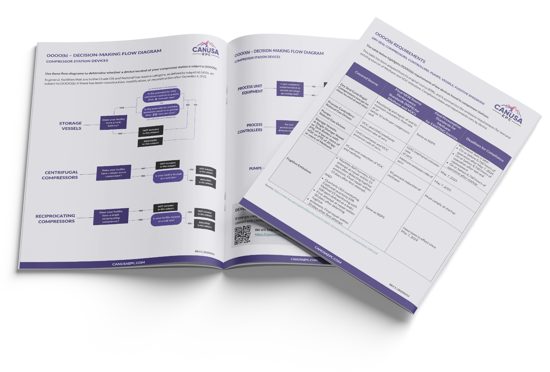
    • Matrix highlighting OOOO(b) requirements of key devices found in compressor stations: dry seal compressors, controllers, pumps, vessels, and fugitive emissions
    • Decision-making flow diagrams to help you determine which OOOO(b) sub-parts pertain to your operation
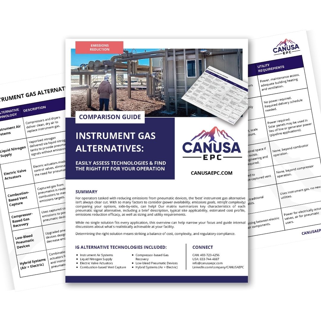
  • Instrument Gas Alternatives Comparison Guide

    Instrument Gas Alternatives Comparison Guide

    Summary

    For operators tasked with reducing emissions from pneumatic devices, the ‘best’ instrument gas alternative isn’t always clear cut. With so many factors to consider (power availability, emissions goals, retrofit complexity) comparing your options, side by-side, can help! Our matrix summarizes key characteristics of each pneumatic signal alternative.

    While no single solution fits every application, this overview can help narrow your focus and guide internal discussions about what’s realistically achievable at your facility. Determining the right solution means striking a balance of cost, complexity, and regulatory compliance.

    This instrument gas alternatives comparison guide includes:

    • Brief Description
    • Typical Site Applicability
    • Estimated Cost Profile
    • Emissions Reduction Efficacy
    • Sizing and Utility Requirements
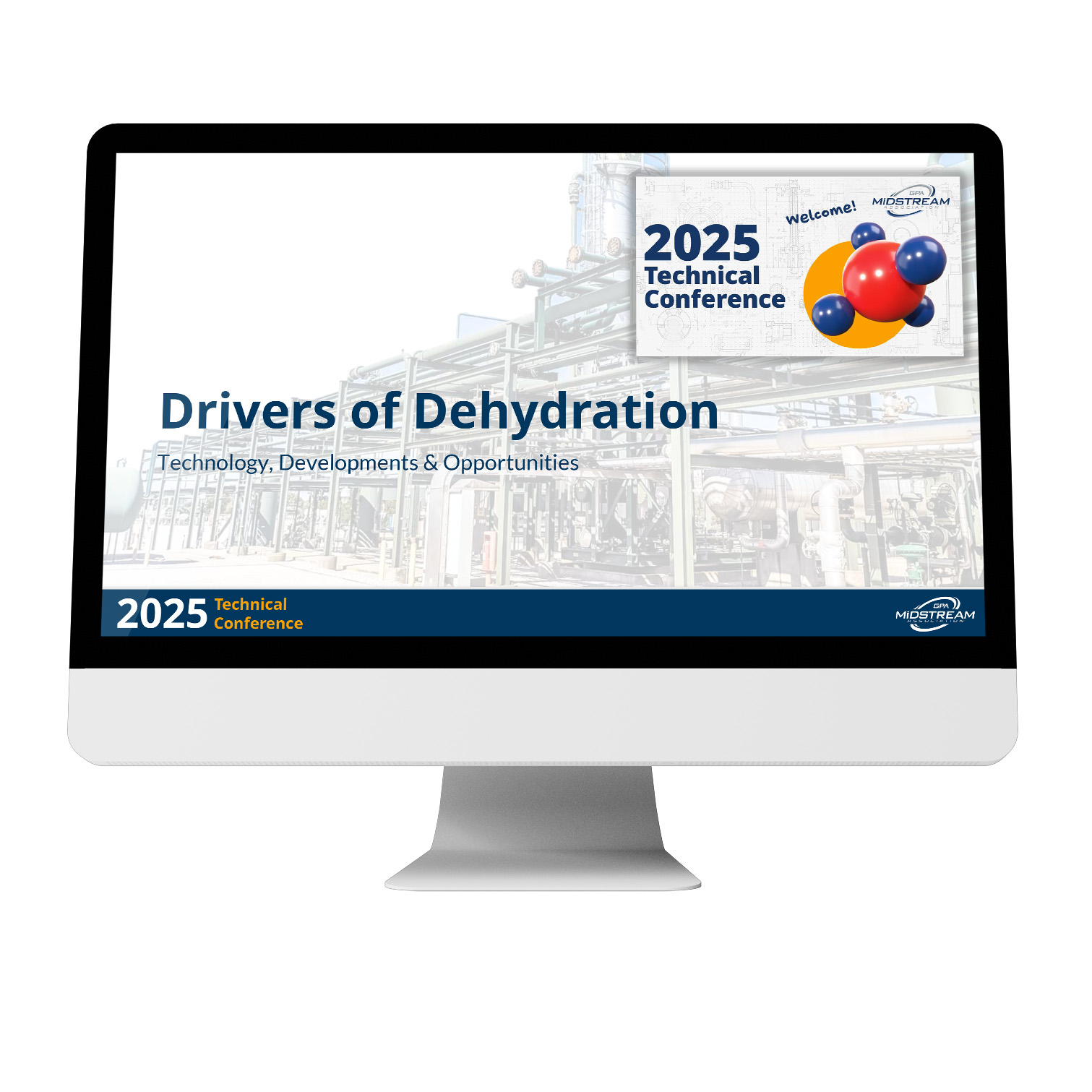
  • Drivers of CO2 Dehydration

    Drivers of CO2 Dehydration

    Summary

    Concerned about water saturated CO2 causing reliability and integrity issues? Trying to determine the right dehydration technology for your CO2 injection project? Download the presentation CANUSA EPC’s Tevin Champagne delivered at the GPA Midstream 2025 Technical Conference.

    Content includes:

    • Understanding dehydration
    • Carbon capture process
    • Traditional dehydration approaches – TEG, chillers, DEXPro & others
    • Comparing dehydration technologies – reliability, CAPEX, OPEX, water content & environmental impact
  • Instrument Gas to Instrument Air Conversion

    Instrument Gas to Instrument Air Conversion

    The Challenge

    The Client needed to convert the instrument gas devices at (4) natural gas compression facilities in Oklahoma to instrument air service in a 6-month period.

    OOOO(b) requires that process controllers emit no identifiable emissions. Instrument air systems are inherently emissions free, so they are not subject to requirements specified in subpart 60.5390b.

    The Solution

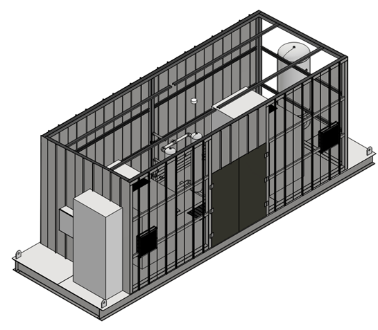
    CANUSA EPC conducted site visits to audit all the instrument gas users at the facility, as-build the P&IDs for IA users, and validate facility electrical capacity to add an instrument air skid. Sizing requirements for the instrument air compressor skid were provided to account for all users and start air for the natural gas compressors.

    The design and construction packages were executed in sequential order to meet accelerated schedule deadlines.

    Engineering

    • Walk down (4) facilities
    • Instrument demand study
      • Start air evaluation
    • Instrument air skid specifications
      • Dual compressor design for
    • Recommend electrical upgrades

    Design

    • Isometric riser details for IA user areas
    • Header design to account for future start air
    • Electrical and utility upgrades

    The Results

    Reduction in fugitive emissions and venting from previous IG users and compression start-up

    • Successfully achieved reduction of all instrument gas users
    • Calculated emissions reduction of 153 MTPY of methane
    • Compliance with OOOO(b) section 60.5390b
    • 25% reduction in engineering design on a site basis
  • Tank Venting Emissions Reduction

    Tank Venting Emissions Reduction

    The Challenge

    The Client was venting excessive vapors from their produced water tank battery due to higher operating pressure in their inlet separator. Operations had determined that the pressure drop between the slug catcher and the storage tank was resulting in entrained gas venting above OOOO(b) limits.

    The Solution

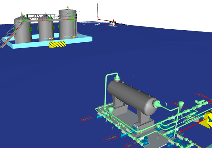
    CANUSA EPC provided engineering and design to install an emission control device. An intermediate knockout drum and combustor were added to the facility. Liquids were routed from the slug catcher to the lower-pressure intermediate knockout, allowing more gases to flash off before sending the remaining liquids to the water tanks. All flashed gases were sent to the combustor.

    Engineering

    • Flare specification
    • Re-purposed knockout drum evaluation
    • Instrumentation and control systems added
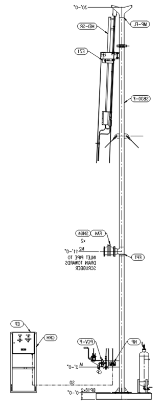
    • Saddle design and flare guy wire anchoring solution

    Design

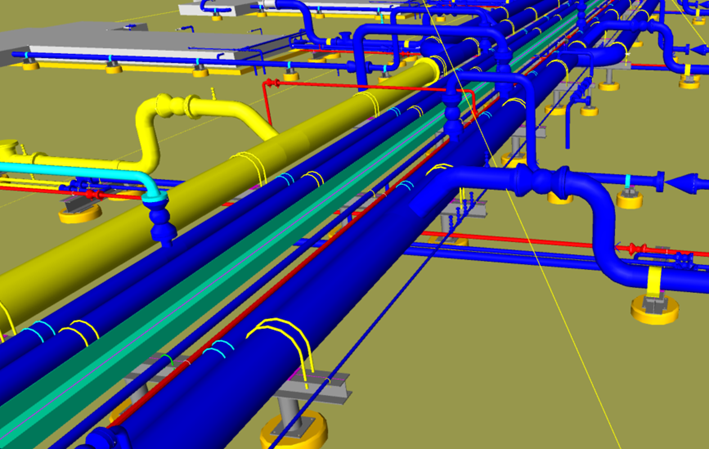
    • 3D Modeling of piping, structural steel, and foundations
    • Piping isometrics
    • Pipe support and foundation details

    The Results

    Reduction in vented vapors from the tank battery

    • Reduced direct venting methane by 10 TPY
    • Alternative solution for recycle of entrained gas to inlet
    • Compliance with OOOOb section 60.5365b(e)